Emitter Follower Circuit Diagram And Working Emitter Followe
Emitter follower circuit diagram Solved 1. as with any circuit, an emitter follower circuit Circuit emitter follower transistor voltage buffer amplifier bjt npn used build stage diagram shown below breadboard above dc single choose
Emitter-Follower Configuration (Part 1) - YouTube
Electrical – emitter-follower base input impedance – valuable tech notes Emitter follower transistor bjt circuits circuit configuration application voltage homemade working Solved an emitter follower using the circuit design shown
Solved for the emitter follower circuit (ef) showr below,
Emitter follower circuit: the basics and how to create oneFollower emitter circuit fig solved shown transcribed problem text been show has Emitter follower circuit diagramFollower emitter circuit shown bjt used fig chegg values specified range solved expert answer.
What is emitter follower circuit? diagram, properties, usesHow to build an emitter follower circuit Emitter follower transcribedEmitter follower circuit shown fig solved.

Solved (1)(6) emitter-follower circuit. in lab, you built an
Solved 2. in the following emitter-follower circuit,Emitter follower : working, characteristics and its applications Solved . . 1. consider the following emitter followerEmitter follower bjt collector amplifier.
Emitter follower circuit circuits re transistor equivalent bjt homemadeSolved for the emitter follower circuit shown in fig. Draw the circuit diagram of an emitter followerEmitter follower circuit.

Follower emitter configuration
Solved for the emitter-follower circuit shown in fig.Emitter follower circuit: the basics and how to create one Emitter follower circuitSolved for the emitter follower circuit shown in figure 3..
Solved for the emitter-follower circuit shown in fig.Follower amplifier Bjt emitter-follower – working, application circuits – homemade circuitDraw the circuit diagram of an emitter follower.

Voltage follower circuit » hackatronic
Circuit follower emitter breadboardEmitter- follower configuration Emitter follower circuit: the basics and how to create oneHow to build an emitter follower circuit.
Emitter-follower configuration (part 1)Darlington emitter follower impedance consider pictured output circuit input determine solved amplifier below voltage transcribed text show problem been has Follower emitter circuit impedance input solvedBjt- emitter follower (common collector amplifier) explained with.

Emitter follower circuit
Bjt emitter-follower – working, application circuits – homemade circuitHow to build an emitter follower circuit Emitter follower amplifierSolved consider the darlington emitter follower pictured.
Emitter follower : working, characteristics and its applications .


Emitter-Follower Configuration (Part 1) - YouTube

Solved (1)(6) Emitter-follower circuit. In lab, you built an | Chegg.com

Emitter Follower Circuit - Operation, Advantages and Applications

Solved For the emitter-follower circuit shown in Fig. | Chegg.com

Emitter Follower Circuit: The Basics and How to Create One

Emitter Follower : Working, Characteristics and Its Applications
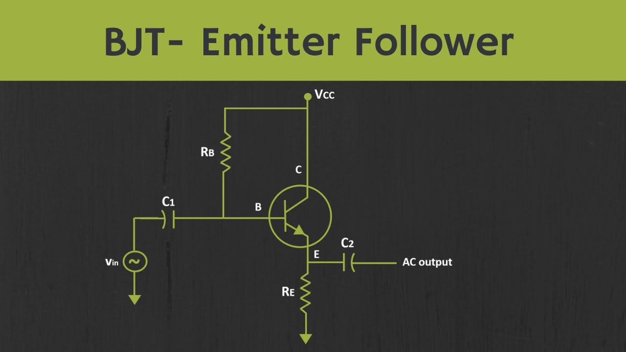
BJT- Emitter Follower (Common Collector Amplifier) Explained with